TABLE OF CONTENTS
- Wiring Diagram
- Spare Parts:
- Install Video:
- Written Guide:
- Tools needed
- Step 1. Power Safety:
- Step 2. Remove the Bottom Panel
- Step 3. Disconnect the Cables on the Mainboard
- Step 4. Unscrew the Mainboard from the Chassis
- Step 5. Remove and Transfer the Thermal Pad
- Step 6. Install the New Main board
- Step 7. Reconnect All Cable to the Mainboard
- Step 8. Reattach the Bottom Panel
Note:
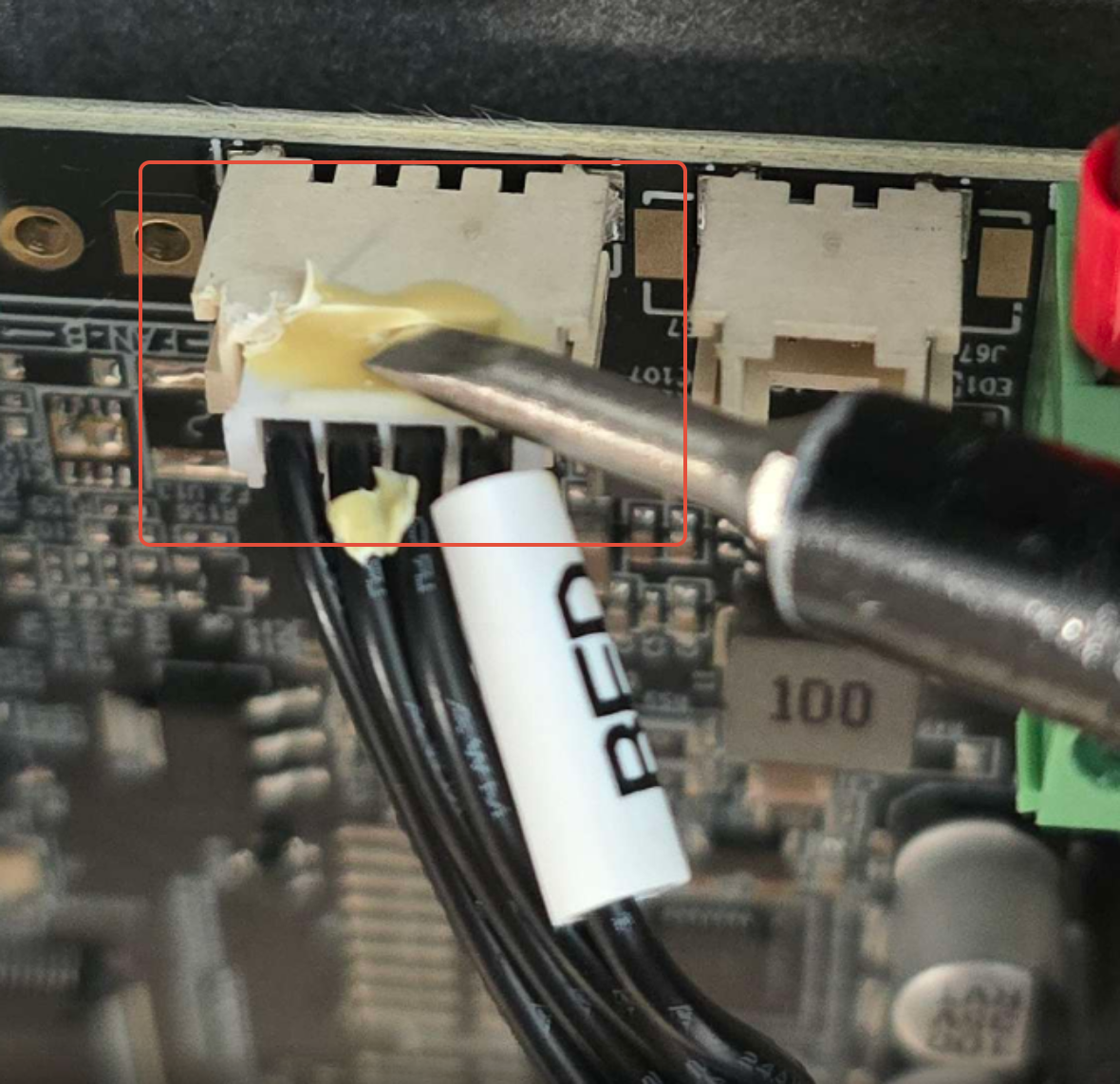
Strong Yellow Glue: Many connectors on the mainboard are secured with strong yellow adhesive. You may need to carefully cut or gently loosen the glue to release the connectors use some 99% iso alcohol onto the glue too loosen connections. Avoid pulling or forcing them, as this can damage both the connectors and the mainboard.
Wiring Diagram
- 24V DC IN
- Z1 Motor
- Z Motor
- Limit Switch Z1
- Limit Switch Z
- Y Limit Switch
- Wifi Antenna
- Screen
- X Motor
- Y Motor
- Nozzle Cable
- RS232 Bed Communication
- ADC BED
- RFID
- Bed Power
- Bed to AC Cable

Spare Parts:
Install Video:
Written Guide:
Tools needed
- 2.5mm Flat Head Driver
- 2mm Hex Driver or Hex Key
- Nippers (for cutting through glue if needed or iso alcohol)
Step 1. Power Safety:
Before starting, ensure the machine is completely powered off and the power cable is disconnected from the printer.
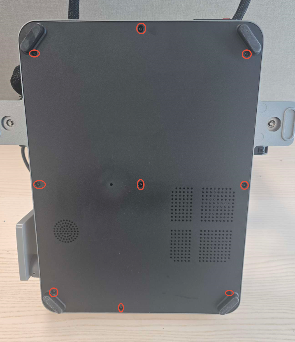
Step 2. Remove the Bottom Panel
Using your 2mm Hex Driver, unscrew the nine screws securing the bottom panel to the chassis. Remove the panel and set it aside. Take care of the electronics fan.
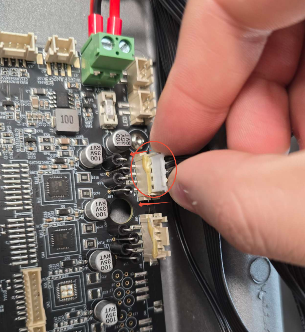
Step 3. Disconnect the Cables on the Mainboard
Begin by loosening the 24V DC terminal block screws to release the power wires.
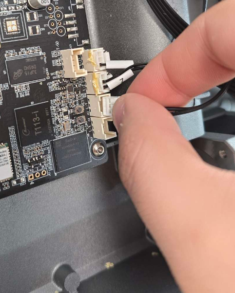
Next, disconnect all remaining cables connected to the mainboard.
⚠️ Note:
Most connectors are glued in place. Carefully cut or peel away the glue before unplugging. Use nippers and a flat head driver to cut or peel the glue, or use some 99% iso alcohol to loosen the glue.
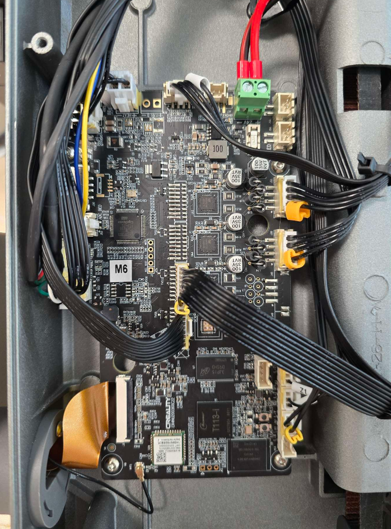
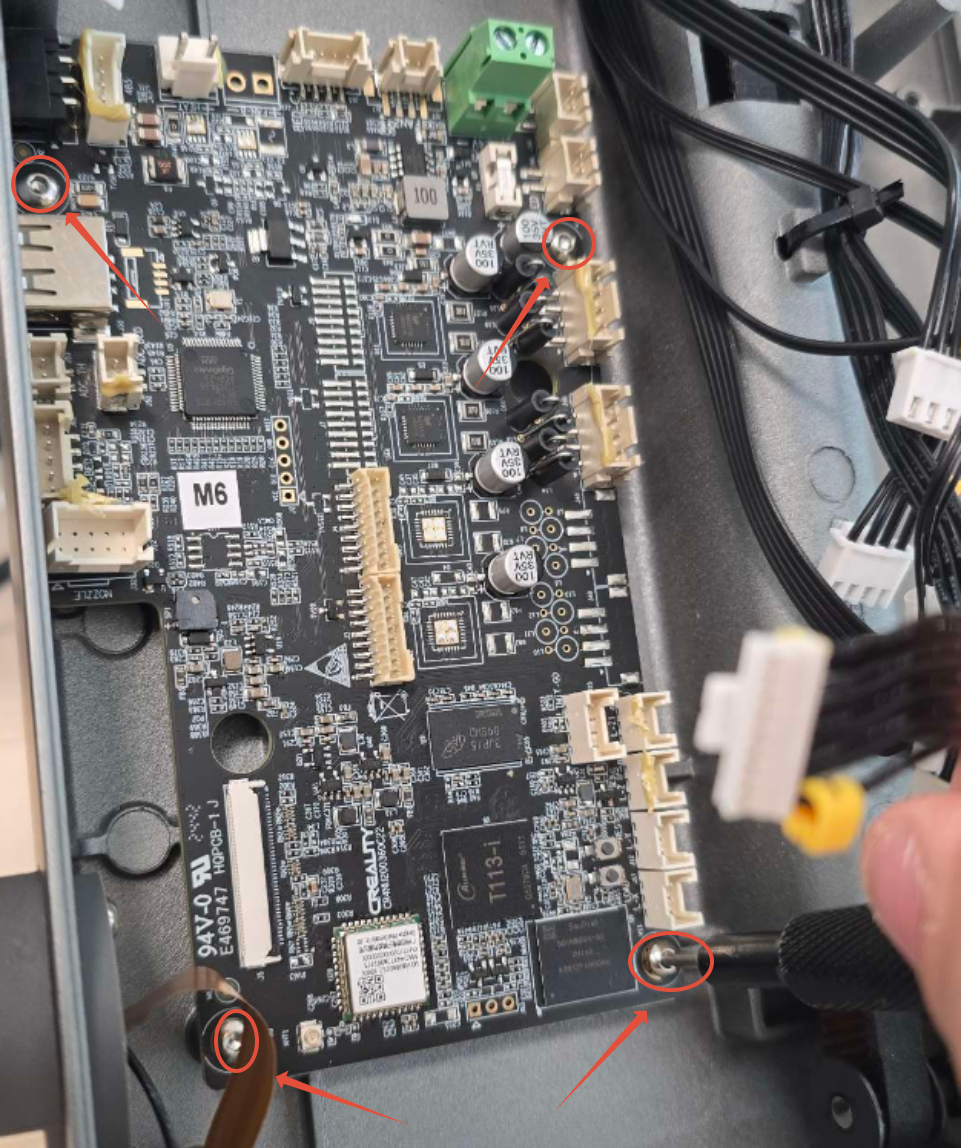
Step 4. Unscrew the Mainboard from the Chassis
Using your 2mm Hex Driver, unscrew the four screws mounting the mainboard to the chassis.

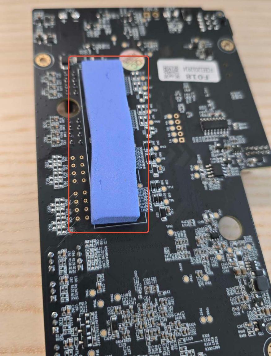
Step 5. Remove and Transfer the Thermal Pad
Flip the old mainboard over and remove the thermal pad from the back. Attach this thermal pad to the same position on your new mainboard before installation.
Step 6. Install the New Main board
Place the new mainboard in position and secure it using the four screws with your 2mm Hex Driver.
Step 7. Reconnect All Cable to the Mainboard
Carefully reconnect all the cables to the new mainboard, ensuring each connection is secure and fully seated.
Refer to the Wiring Diagram below if you’re unsure about cable placement.

Step 8. Reattach the Bottom Panel
Reinstall the bottom panel and secure it using the nine screws with your 2mm Hex Driver.

Was this article helpful?
That’s Great!
Thank you for your feedback
Sorry! We couldn't be helpful
Thank you for your feedback
Feedback sent
We appreciate your effort and will try to fix the article