Overview
The Creality Ender Upgrade Kit is offered in two different versions. In both versions, Copperhead® - No Heater/Sensor and Copperhead® - 50W Heater/300°C Thermistor, you will receive one pre-assembled Slice Engineering Copperhead Hotend. Each hotend will include the following: Copperhead® Heat Break (C-E), Copperhead® Hot Block, BridgeMaster® Nozzle (0.4 mm), Copperhead® Silicone Boot, and a dowel pin.
The Copperhead® - No Heater/Sensor kit, as the name implies, does not include a pre-installed heater or sensor. This option allows you to use the existing heater and sensor on your printer, resulting in a quicker overall installation process, no firmware updates, and no fiddling with cables or motherboards. Because of this, we also include our Boron Nitride Paste with this kit to allow you to install the existing heater and sensor into your new Slice Engineering hotend.
Our DREMC kit comes with pre installed ferruled 24V 50 Watts with 100K rated up to 300c, it require some firmware change to support the whole temperature range or if you not comfortable with firmware flashing/compiling you can always leave it stock, but you will be limited by max temperature. Both are crimped to suitable for direct swap for Ender 3/Ender 5 (non plus, you will need larger 2m extension kit).
The Copperhead® - 50W Heater/300°C Thermistor comes with a pre-installed Custom Industrial Heater - 50W 24V / 1220 mm / Ferrule and Custom Thermistor - 300°C / 1220 mm / JST XHP-2. Both the heater and sensor are preinstalled in the hotend and arrive ready to use. The ends of both the heater and sensor have the appropriate connectors making this a direct "plug and play" replacement to the stock heater/sensor. This setup will allow you to achieve higher printing temperatures, up to 300°C, with the correct firmware updates. Preconfigured firmware files can be found at "Firmware Projects" from Insanity Automations.
This guide will go over the installation steps involved for both types of hotend upgrades previously mentioned. Because of this, some steps outlined below may not be required for your particular installation. The instructions below can also be used to upgrade your Copperhead® - No Heater/Sensor kit with Slice Engineering heaters/ sensors in the event you already have the Slice Engineering hotend but not the heater/sensor combo.
TABLE OF CONTENTS
- Overview
- Video:
- Materials
- Tools (not provided)
- 1. Removal and Disassembly of the Existing Hotend
- Removal of existing heater and sensor
- Installation of the Copperhead® Hotend
- Installing a Heater/Sensor in the Motherboard
- Final Notes
Video:
Materials
Copperhead® - No Heater/Sensor (if using existing heater and sensor)
- Copperhead® Hotend w/ Copperhead® Silicone Boot and Dowel Pin
- Boron Nitride Paste w/ Applicator Swabs
Copperhead® - 50W Heater/300°C Thermistor
- Copperhead® Hotend w/ 50W Heater/300°C Thermistor
Optional (if upgraded your Copperhead® - No Heater/Sensor with a Slice Engineering heater and/or sensor)
- Custom Industrial Heater - 50W 24V / 1220 mm / Ferrule
- Custom Thermistor - 300°C / 1220 mm / JST XHP-2
Required but not provided with the upgrade kit
Stock Creality, or aftermarket, heat sink that will accept a stock Creality heat break. Must include a setscrew (see picture)
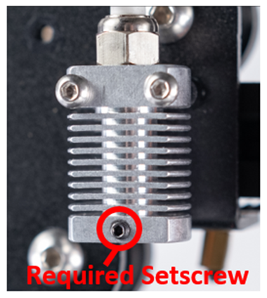
- Heater (if installing the Copperhead® - No Heater/Sensor Kit)
- Sensor (if installing the Copperhead® - No Heater/Sensor Kit)
Tools (not provided)
- Philips Head Screwdriver
- 1.5 mm hex key
- 2.0 mm hex key
- Diagonal Cutting Plier (if installing a new heater or sensor)
- Flat Head Screwdriver (if installing a new heater or sensor)
1. Removal and Disassembly of the Existing Hotend
 Prior to removing the current hotend you may find it easier to remove any filament that is currently loaded. While this is not required, it will make the process easier. Follow all normal safety steps while removing filament from the hotend.
- Ensure the hotend has been allowed to cool down to ambient temperatures.
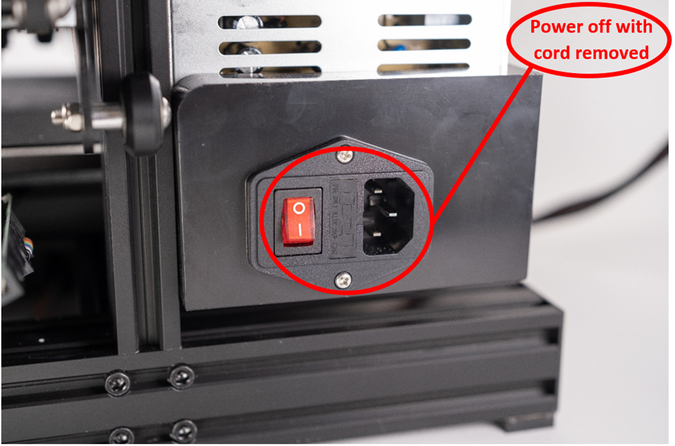
- Turn off the power to the printer and remove the power cord.
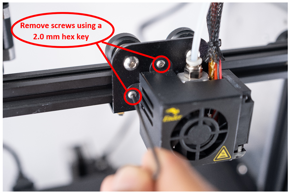
- Using a 2.0 mm hex key, remove the two screws attaching the fan housing to the gantry plate
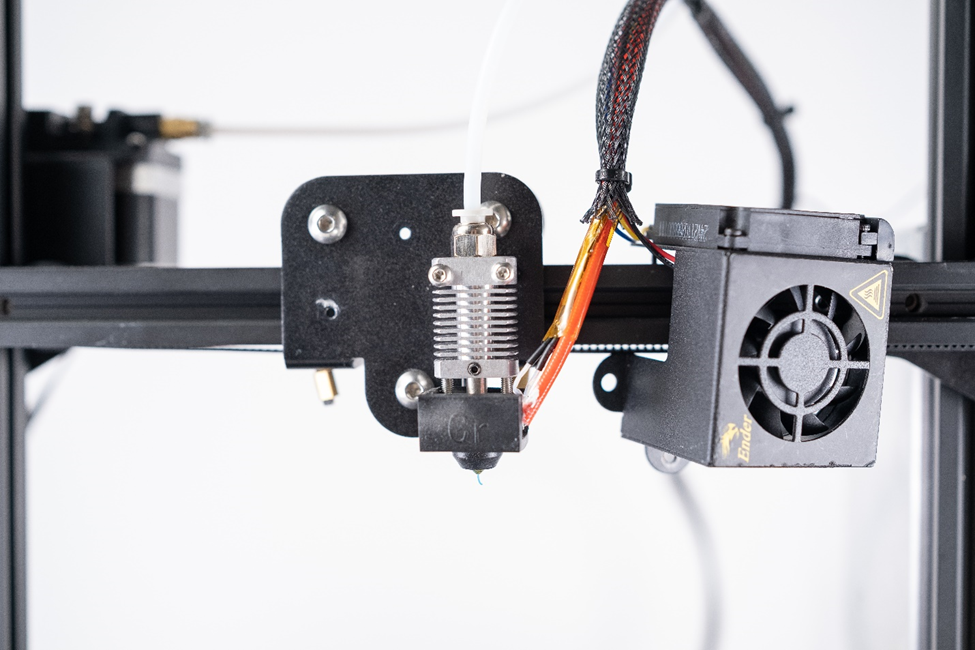
- Set the fan housing to the side
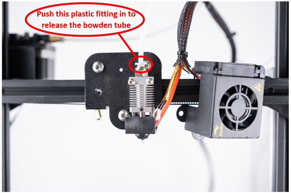
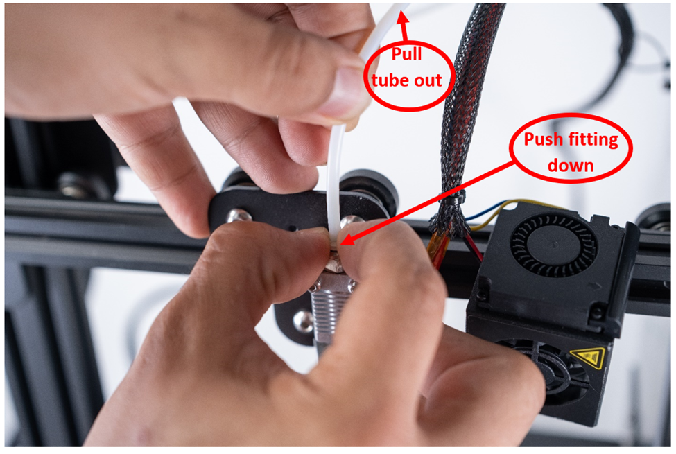
- Remove the Bowden tube from the heat sink by pushing down on the top of the pneumatic fitting. This will allow the Bowden tube to be pulled out. This step can be performed at any time prior to installing the Copperhead hotend.
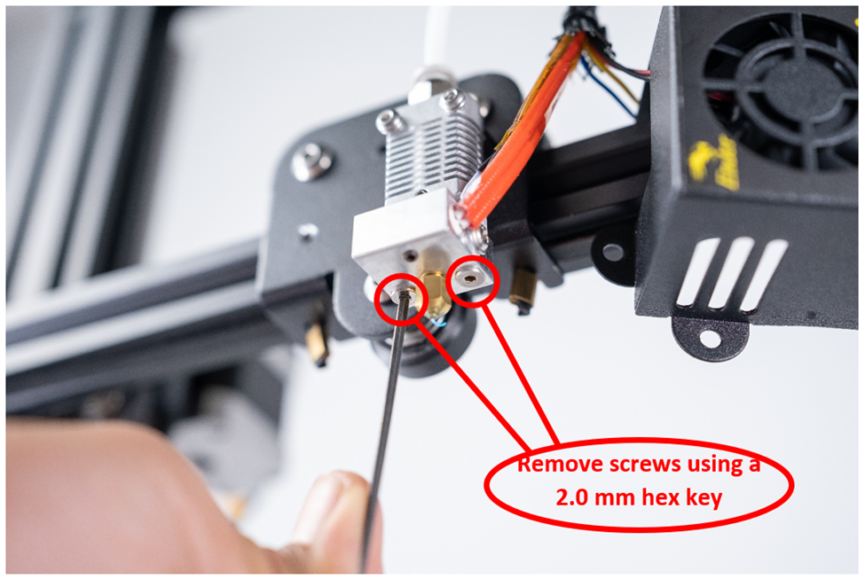
- Using a 2.0 mm hex key, remove the two screws located at the bottom of the hotend
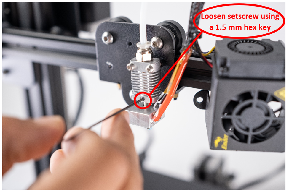
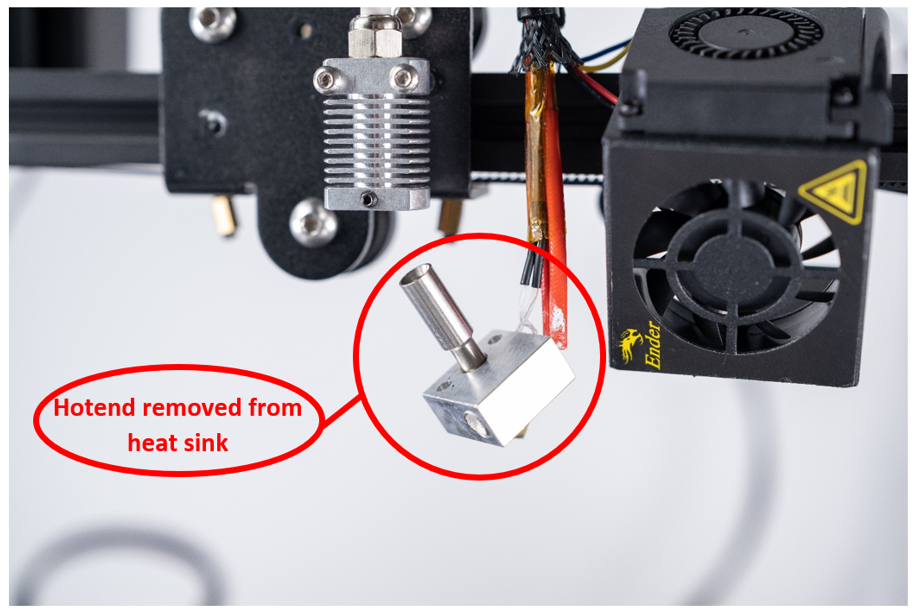
- Using a 1.5 mm hex key, loosen the setscrew on the heat sink to release the hotend.
- Gently pull the hotend out of the heat sink.
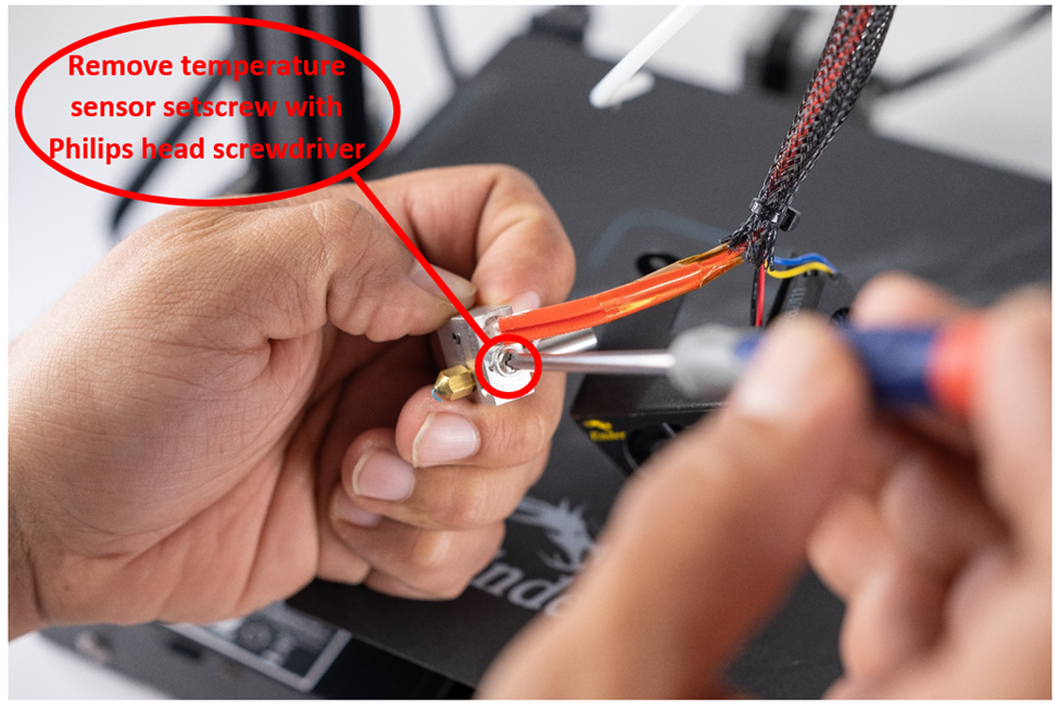
- Using a Philips head screwdriver, remove the temperature sensor setscrew from the hot block and gently remove the temperature sensor.
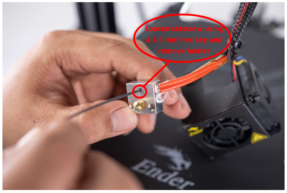
- Using a 1.5 mm hex key, loosen the setscrew on the bottom of the hot block and gently remove the heater from the hot block.
Removal of existing heater and sensor
 NOTE: This step is only required if you will be installing the Copperhead® - 50W Heater/300°C Thermistor Kit or a Slice Engineering heater and/or sensor.
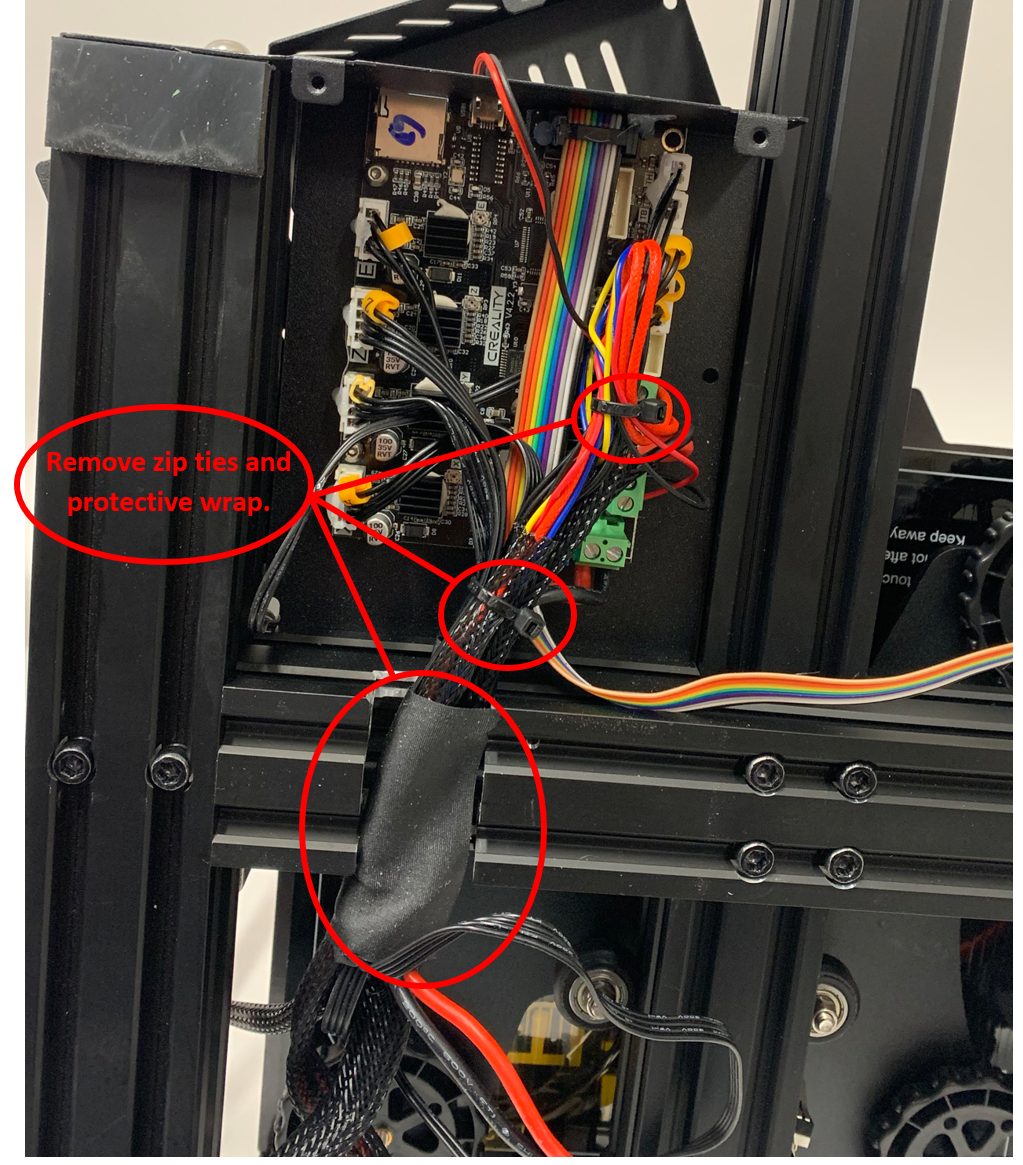
Using a pair of diagonal cutting pliers, remove any zip ties that are sinching the mesh cable sleeving to the wiring running from the hotend to the motherboard.
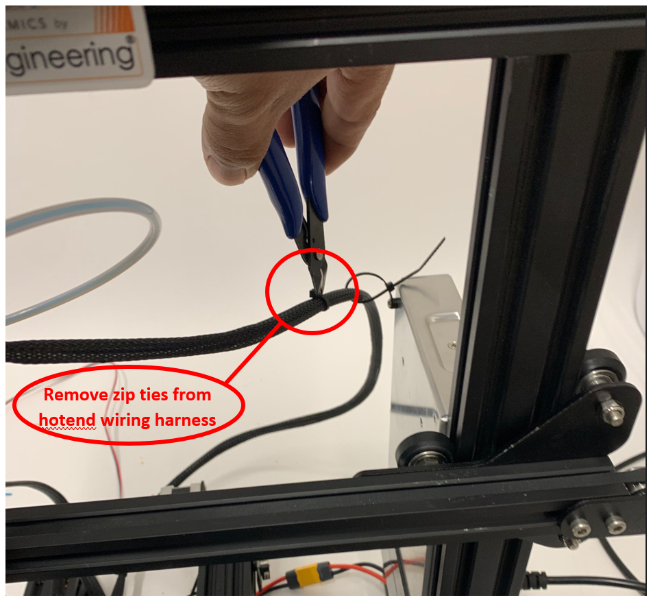
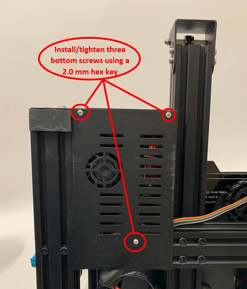
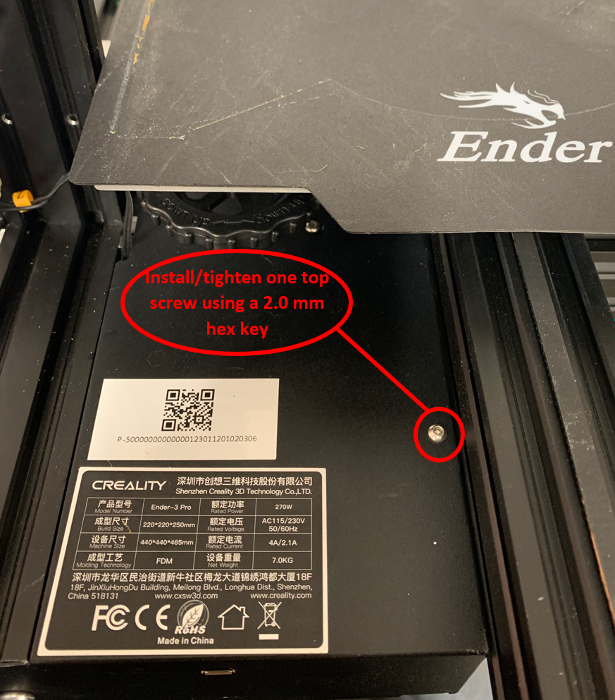
- Using a 2.0 mm hex key, remove the 4 screws, 3 on the bottom of the machine and one on the top, used to hold the metal cover over the motherboard.
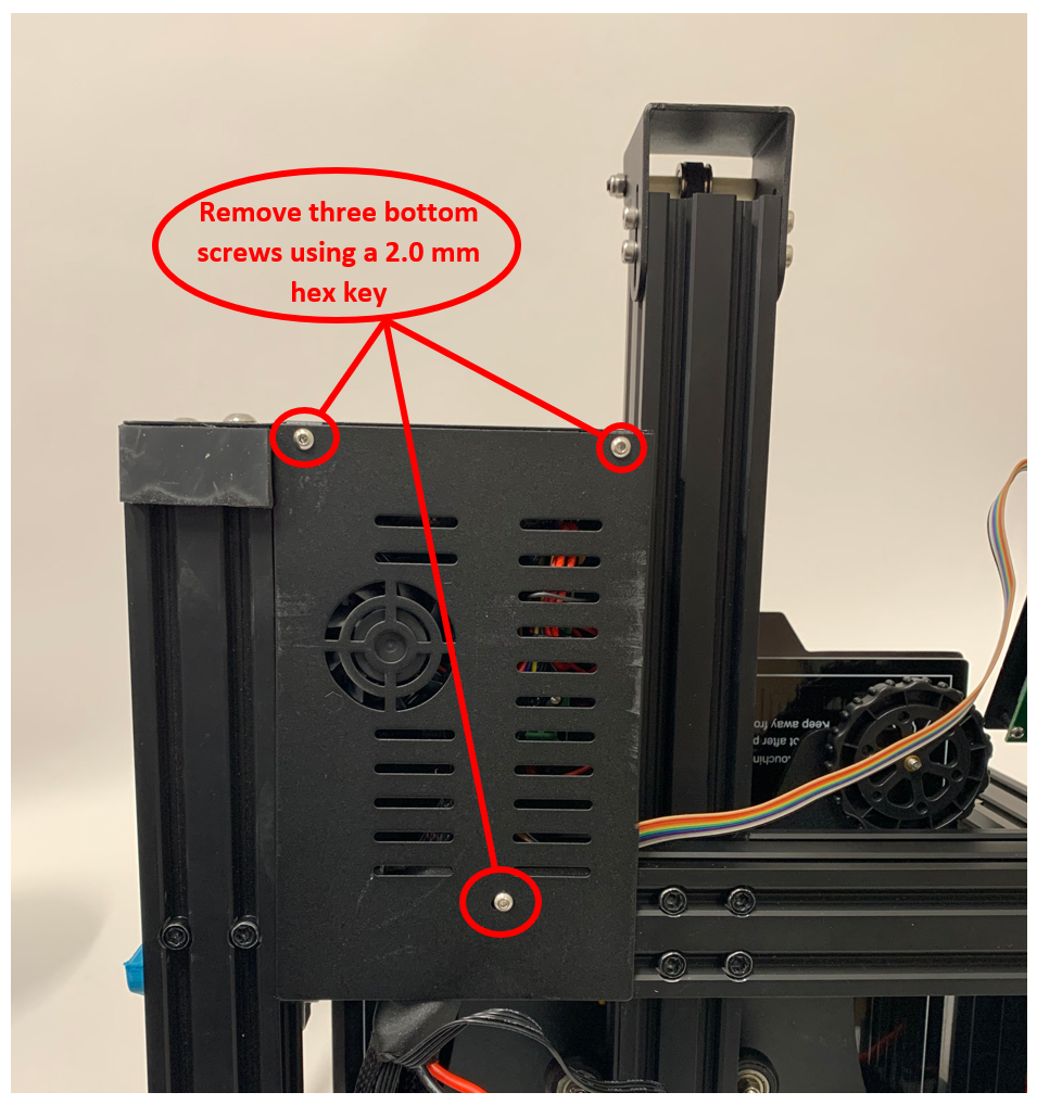
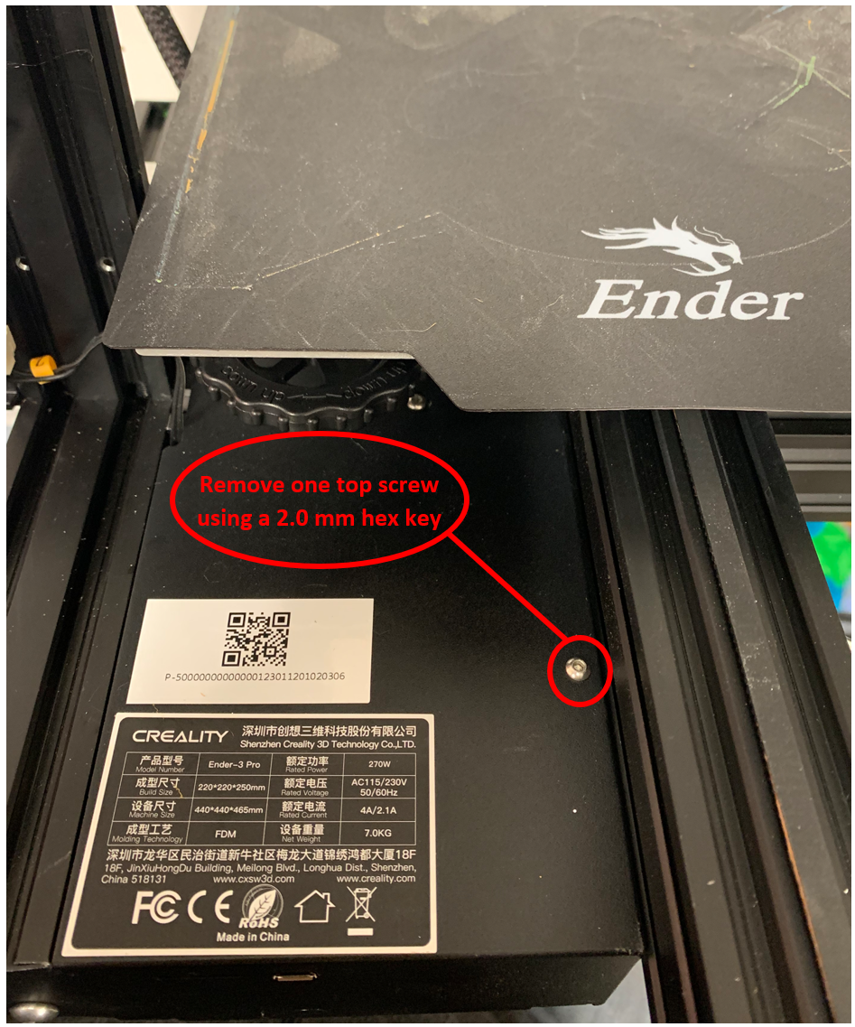
With the cover removed, remove any additional zip ties or wraps that are constraining the hotend wiring harness.
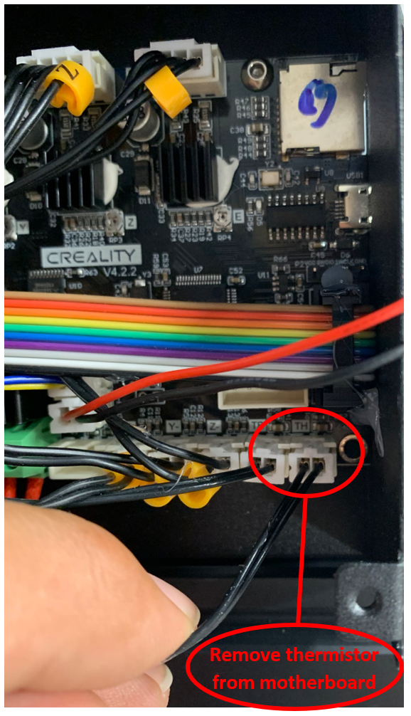
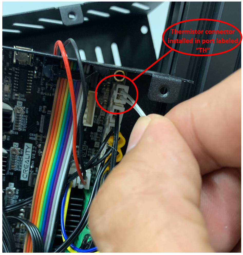
- Unplug the stock thermistor from the motherboard. As depicted, this will be the "TH" port on the 4.2.2 motherboard.
- Using a small flat head screwdriver, unscrew the two posts clamping the heater leads to the motherboard. Once these two posts are loosened you can remove the heater leads from the motherboard.
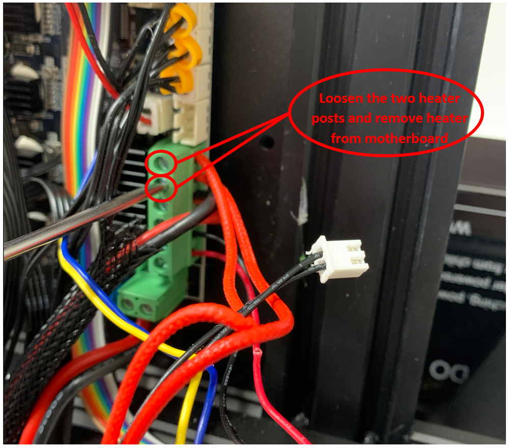
Remove the heater and sensor from the mesh cable sleeving. This can be easily done by bunching up the mesh cable sleeving and gently pulling the heater/sensor out.
Installation of the Copperhead® Hotend
 NOTE: Steps 1 thru 8 are only required if installing the Copperhead® - No Heater/Sensor hotend
- Remove the Copperhead® Silicone boot from the hotend.
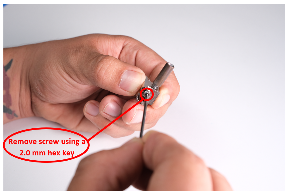
- Using a 2.0 mm hex key, remove the retaining screw located on the side of the Copperhead® hotend, to the left of the Slice Engineering logo.
 Care must be taken to not lose the dowel pin located inside the hot block. Only the indicated retaining screw should be removed, pictured below. This will ensure the heater and sensor are routed the correct way to allow proper installation of the hotend into the heat sink/printer. Do not grip the heat break when removing the retaining screw as doing so may cause damage to the heat break.
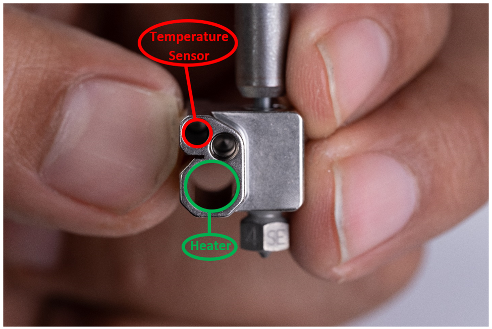
Remove the cap from the syringe of Boron Nitride Paste. Push the open end of the syringe onto the small temperature sensor hole and fill the hole with Boron Nitride paste. This will be done on the side you removed the retaining screw from. Any excess Boron Nitride Paste can easily be clean after installation with a damp paper towel/ Q-tip
.
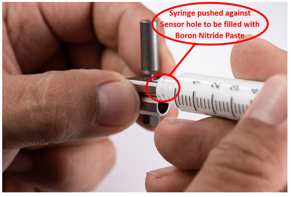
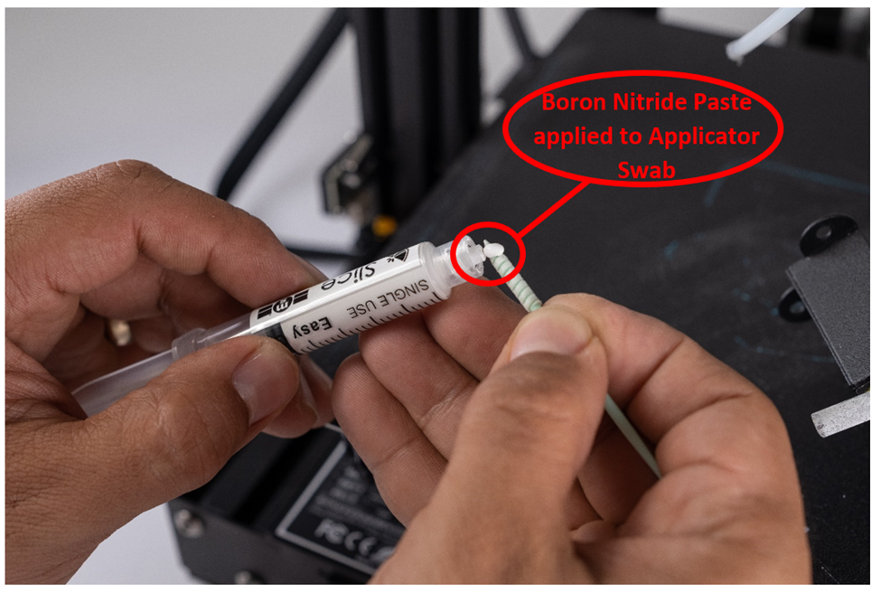
- Dispense a pea-sized amount of Boron Nitride Paste onto an applicator swab.
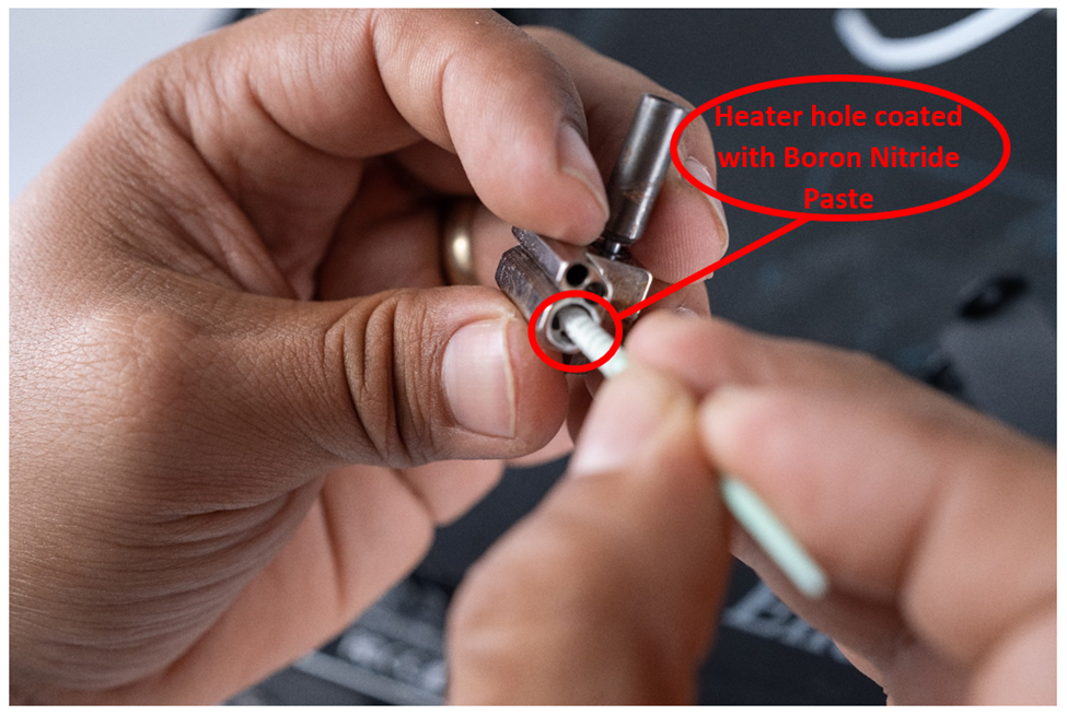
- Using the Boron Nitride Paste on the applicator swab, coat the interior of the heater hole with paste.
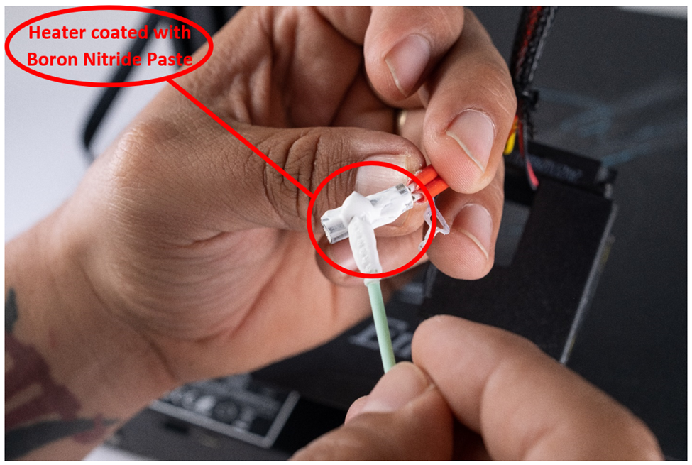
- If needed, apply more Boron Nitride Paste to the applicator swab and then coat the heater cartridge with paste.
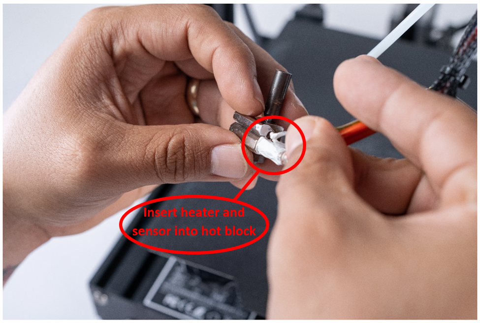
- Insert the heater and temperature sensor into the hot block. An applicator swab can be used to clean up any excess Boron Nitride Paste on the exterior of the hot block.
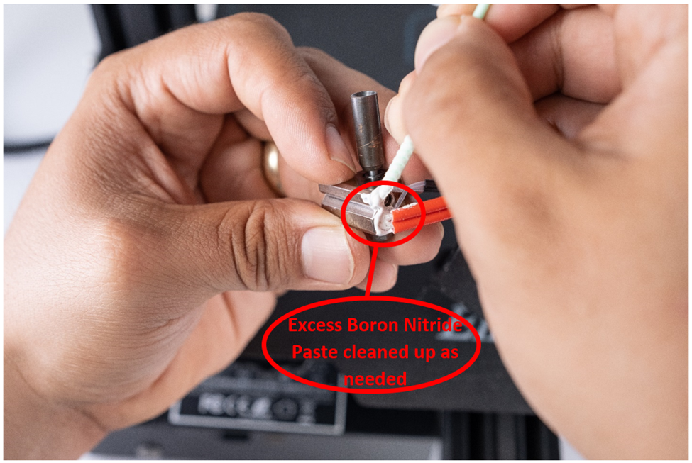
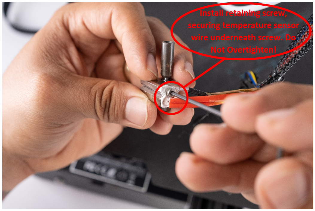
- Using a 2.0 mm hex key, reinsert and tighten the hot block retaining screw. The retaining screw is used to hold the temperature sensor wire in place, as well as to retain the heater. Do not overtighten the retaining screw as this may damage the temperature sensor wire.
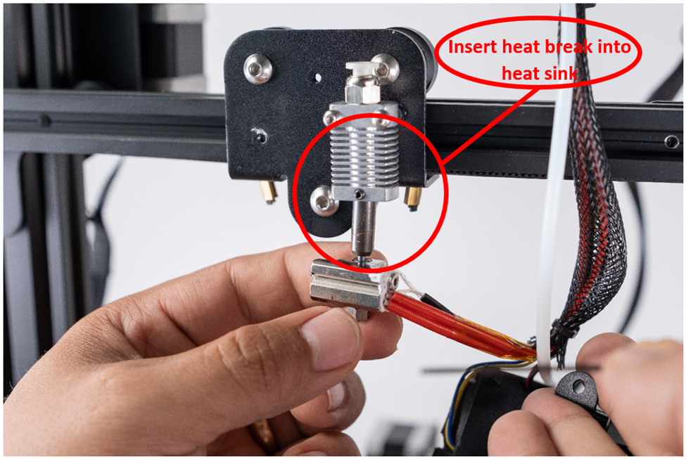
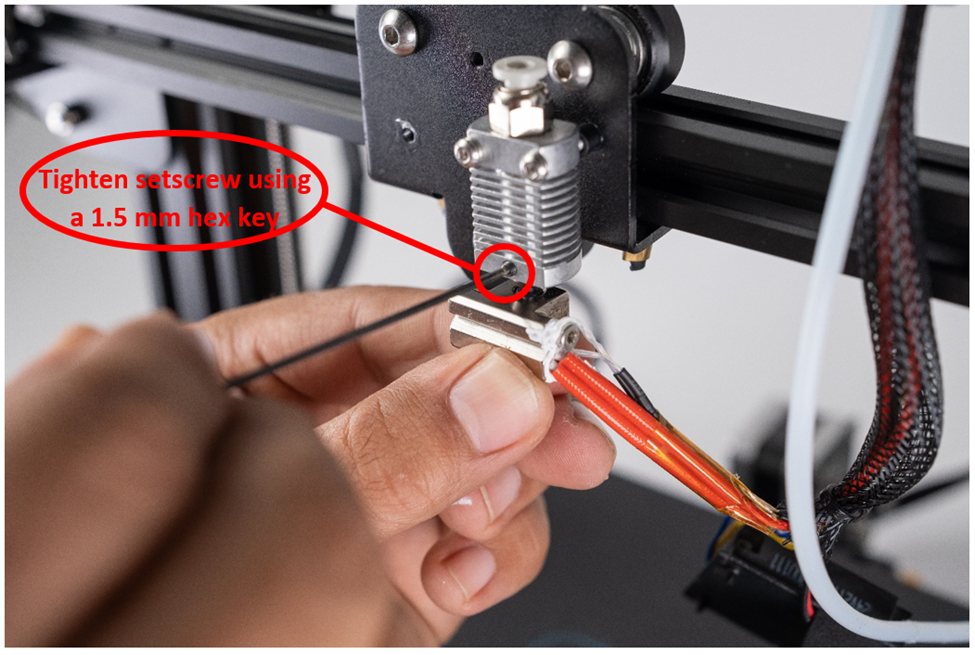
- Insert the hotend into the heat sink until it comes to a stop. With the stock heat sink, the fully inserted heat break will remain ~1.5mm out of the heat sink. Using a 1.5 mm hex key, tighten the setscrew on the heat sink to secure the hotend.
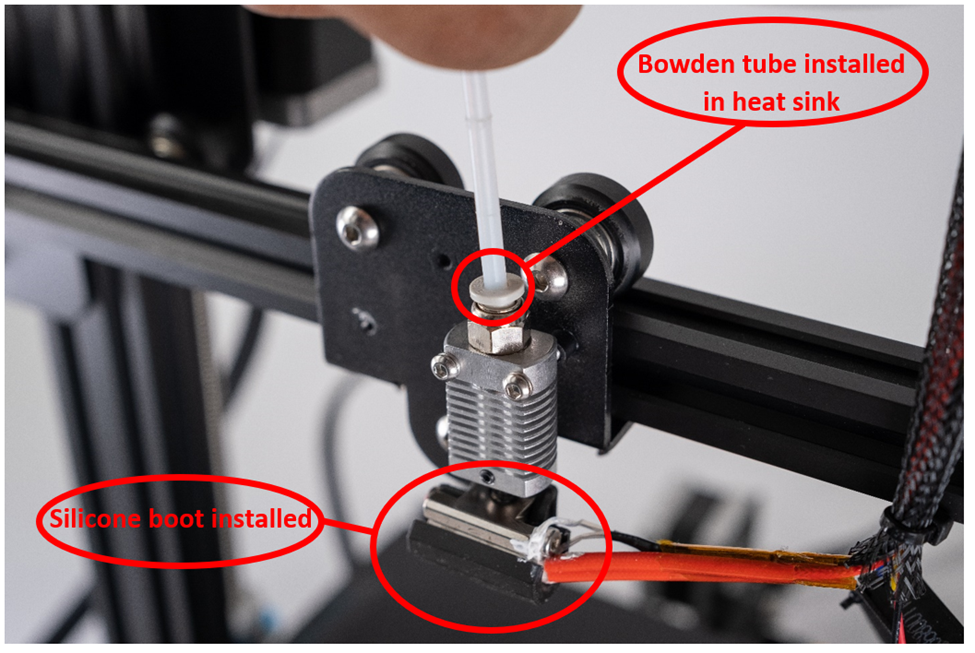
- Reinstall the Copperhead® Silicone Boot and Bowden tube.
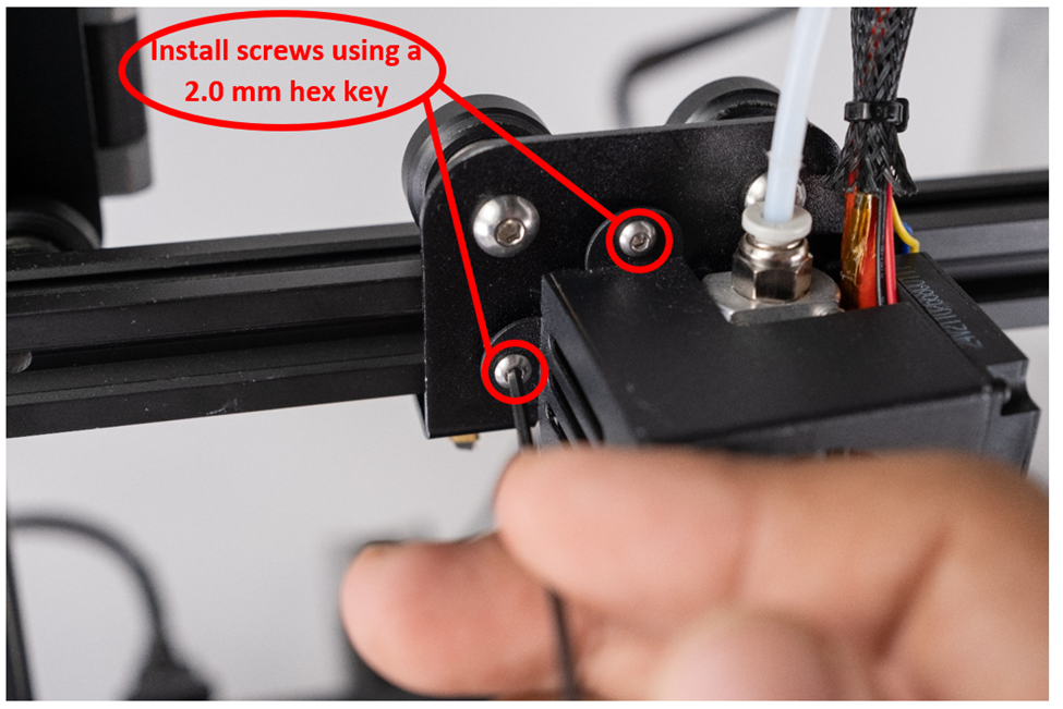
- Using a 2.0 mm hex key, reinstall the fan housing.
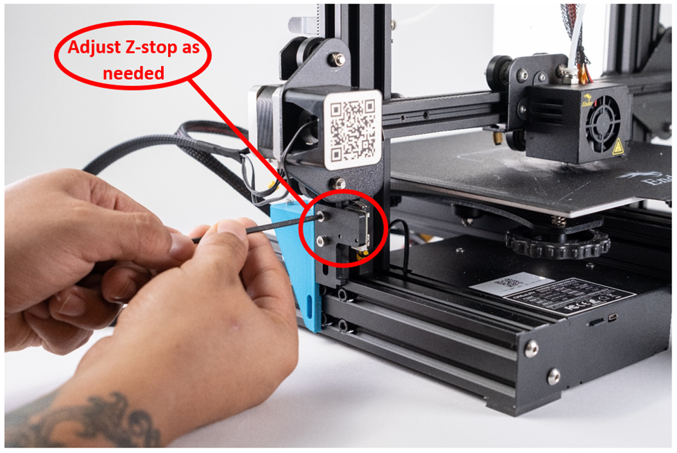
Adjust Z stop to the height of the new hotend.
 NOTE: If installing the Copperhead® - 50W Heater/300°C Thermistor kit skip steps 13 and 14 below. Proceed to the section below titled "Installing a Heater/Sensor in the Motherboard."
- Plug in the power cable and turn the machine on.
- PID tune your newly installed Copperhead® hotend.
Installing a Heater/Sensor in the Motherboard
 NOTE: The steps in this section are only required if installing a Slice Engineering heater or sensor.
- Pass the Slice Engineering heater and sensor cables through the mesh cable sleeving by bunching up the mesh cable sleeving and pushing the cable through from the hotend side of the mesh cable sleeving to the motherboard end.
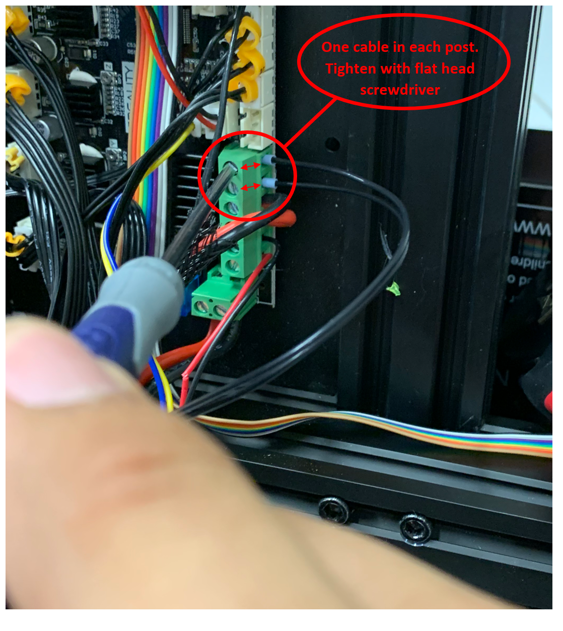
- Insert the ferrule ends of the heater cable into the hotend heater post on the motherboard, one end in each post. With the ends insert, using a flat head screwdriver, tighten the post to secure the heater to the motherboard.
- Insert the thermistor connector into the thermistor port, labeled "TH", on the motherboard.
- Zip-tie and wrap the cables as needed.
- Replace the motherboard cover. Using a 2.0 mm hex key, install the 4 screws that secure the cover to the printer.
- Plug in the power cable and turn the machine on.
- PID tune your newly installed Copperhead® hotend.
Final Notes
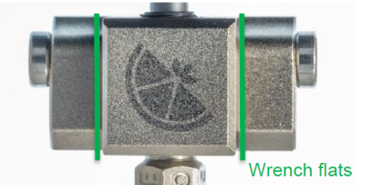
 When changing the nozzle we recommend the use of our 1.5 nm Nozzle Torque Wrench to prevent plastic leakage. To change nozzles, grasp the Hot Block wrench flats shown below with a wrench, and then tighten, or loosen, the nozzle. The hot block must be held in place when changing nozzles to prevent any accidental damage to the hotend.
 The table listed below is a recommended starting point for certain slicer settings when using this upgrade. It is best practice to calibrate your slicer settings when using new components/filaments. This is most commonly done by printing a temperature tower and retraction tests. All listed specifications are based on the use of a 0.4 mm nozzle. The suggested settings below can, and in most cases should, be adjusted to optimise your particular printer's performance.
| Material Type | Retraction Distance | Perimeter Speed | Infill Speed |
| PLA | 2.0 mm | 80 mm/s | 100 mm/s |
| PETG | 2.0 mm | 60 mm/s | 80 mm/s |
Was this article helpful?
That’s Great!
Thank you for your feedback
Sorry! We couldn't be helpful
Thank you for your feedback
Feedback sent
We appreciate your effort and will try to fix the article